Making a 12-volt strip light run on LEDs instead
We adapted our old 12-volt strip light unit to instead use an array of 12-volt LEDs, to benefit from considerably lower power consumption and more importantly never needing to buy or replace a bulb ever again! As an electronics hobbyist who is not a professional but who already does their own boat DC electrics, projects like this are totally achievable but are still best left to someone who has a proficiency and understanding of 12-volt electrics. MAINS ELECTRICS IS A COMPLETELY DIFFERENT MATTER AND SHOULD NEVER BE INTERFERED WITH EXCEPT BY A PROFESSIONAL! Before attempting this yourself, first take care to read through the instructions in full, and make sure you have the necessary minimal skill and equipment for doing the task safely and sufficiently well. Please don't blame us when you blow up your boat - this report is only to show how we did this, it's not telling you that you should go and do it and then come over all blamey after your own doing of any of it wrong then caused some kind of problem or loss - it comes with absolutely no guarantees!
Image 0
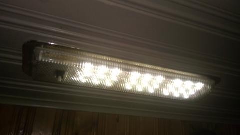
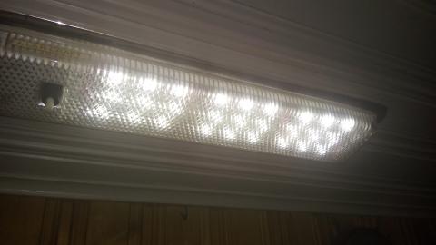
This is the replaced light now working with 12-volt LEDs. The LEDs used are for use in cars and vans so having the necessary integral chip for voltage regulation, they come in a set of ten bars of three LEDs all joined in parallel but as a string, making them very easy for placing into the old striplight housing. Here is a link to the kind of LEDs, so that you can see some terms for searching-for to be able to find them for sale online: https://www.amazon.com/AZKQJ-Interior-Caravans-Trailers-Sprinter/dp/B074J7N2QX
Image 1
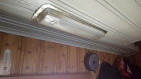
This is the kind of strip light unit that we will adapt, the common Labcraft three-bulb strip light unit that most boaters only use with one bulb per unit, to keep the power consumption down and reduce the number of bulbs constantly malfunctioning, overheating and blowing all the time.
Image 2
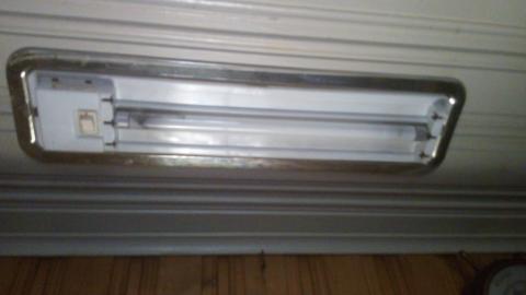
First switch-off the light, and also switch-off the power supply at the fusebox. Remove the bulb cover, which can be quite difficult to do without damaging the unit but try to do it properly anyway. Although they are usually intended to be removed by levering a flat-headed screwdriver beneath the cover at one end, we find it is easiest to pry-open the cover from the centre towards the end by sliding a thin flexible knife, or a flathead screwdriver or a spudger, along the thin gap between the cover and the white plastic housing. Take care not to pry the housing away from the ceiling or it can break the thin plastic screw-retainers that are part of the housing and will cause the unit to irreparably fall-away from the ceiling! The bulb cover should come away leaving the housing still attached to the ceiling.
Image 3
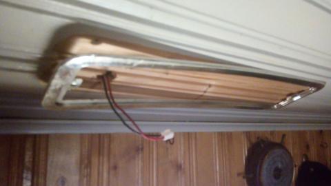
Then unscrew the light fitting from the ceiling by removing the screw that attaches each end of housing, and disconnect the wiring from the fitting. If you have had to cut the power lead wires, now might be a good time to separate them and fix them into a connector, to avoid accidental short-circuit and damage to your lighting power cabling should you go reactivating the rest of the lighting circuit while there are wires hanging all over the place. We prefer crimped molex-style connectors, which are good for separating the positive and negative while affording easy re-connecting and disconnecting. Others often use choc-blocks, but many boaters frown on choc-block use for their unreliability under vibraton stresses and for their tendancy to suffer from corrosion in damp conditions and/or from disimilar metals.
Image 4
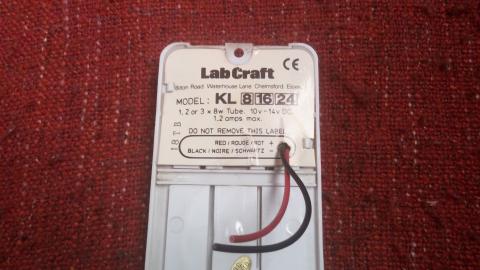
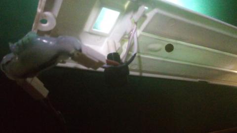
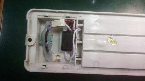
This is where the circuitry for powering the strip lights is contained, beneath the thin plastic cover with the printing on. Remove this, but retain the plastic cover because we will be reusing it when we have added replacement components for powering the LEDs.
Image 5
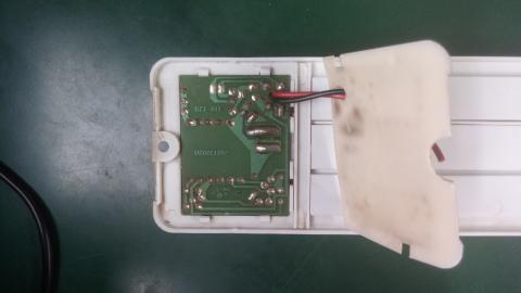
You will need to pry out the old circuit board - you won't be reusing this circuit board so it is ok if you damage it while getting it out, however you will be reusing the switch (if it survives the removal process) and you will find that the electrical connectors to the switch are fixed with heavy soldering to the board, however removing the solder with heat can damage the plastic of the switch so it is best to instead forcibly lift these connections out of the switch by pulling the circuit board directly outwards (i.e. towards the camera in the photo) in a manner that causes these connections to break away out of the switch. Then you can de-solder the detached switch connections without melting the switch itself, and then re-fit them into the switch after the desoldering. Try not to damage the enclosure or the white plastic surrounds because you will be reusing the space revealed inside for housing some replacement parts for powering the LEDs.
The thin plastic cover shown here can be reused in its original place for preventing the replacement parts from falling out of the enclosure, with a corner cut-away from it to expose the connection for rejoining onto the power leads.
Image 6
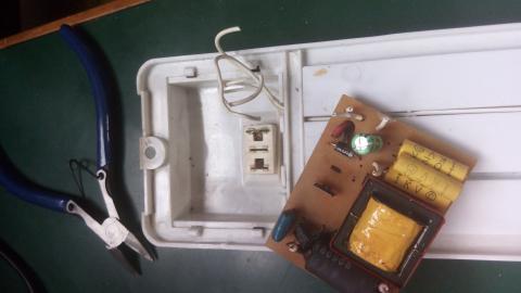
Here is the old circuit board removed with the switch still in-place. The switch connectors remained on the circuit board (one of them can still be seen on the board in the photo. De-soldering the switch connections from the boards is best done away from the plastic switch itself, as described earlier). You should dispose of the old circuit board properly, or first harvest the parts off it if you are into reusing old components for random electronics projects, otherwise simply recycle the whole thing.
Image 7 and image 8
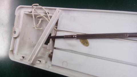
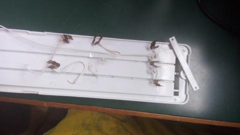
Prise-off the thin plastic rectangles that retain the striplight wiring and connectors, and completely remove the wires and connectors (they should simply pull-out once each retainer is removed) - keep the retainer that fitted nearest the enclosure, as you will be putting that one back in-place, once the LEDs are positioned.
Image 9
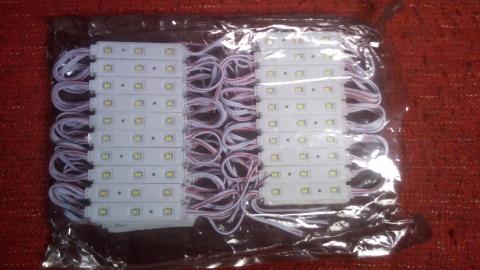
These are the kind of LEDs that you will be using to replace the striplights. Ours came in packs of ten sets, where each set is ten bars of three LEDs all connected in parallel (we will be using nine bars from one set, and will keep the tenth bar for replacing a bar when/if it fails, eventually). We got this pack of ten sets (each set has ten bars of three LEDs) at a car boot fair for five pounds for the whole pack !!
Image 10
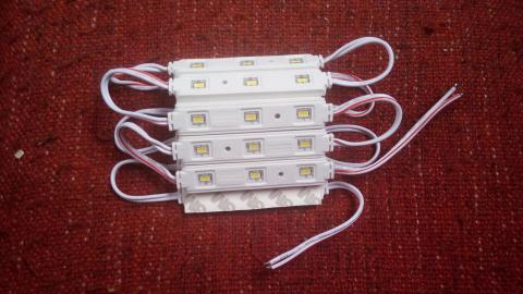
This is the set of ten three-LED bars, which come ready connected in parallel and have a peelable sticky back to them.
Image 11
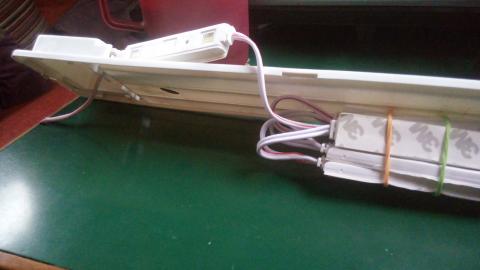
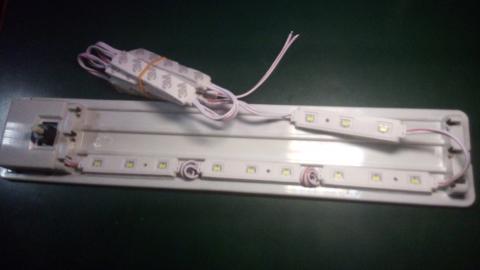
You can poke the wiring from the endmost LED bar into the component enclosure, with the LEDs on the outside where the strip lights used to go. The existing holes in the housing are usually suficient for this without any need to cut into anything. We will position the rest of the connected LEDs after we have got the rewiring working properly (to avoid sticking everything down only to find that something is not working correctly).
Image 12
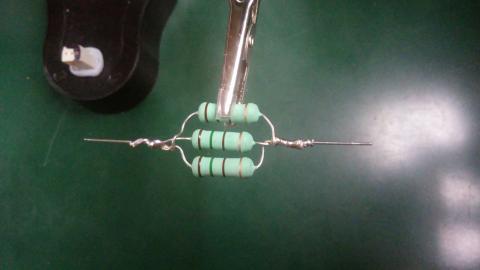
Now for making the replacement circuitry for powering the LEDs. Join three 150-ohm resistors in parallel like this and solder them together for decent connectivity. We are using these three 150-ohm resistors in parallel to create a combined resistance of only 50-ohms, while allowing the resistors to dissipate their heat more effectively than if one 50-ohm resistor were used on its own.
Image 13
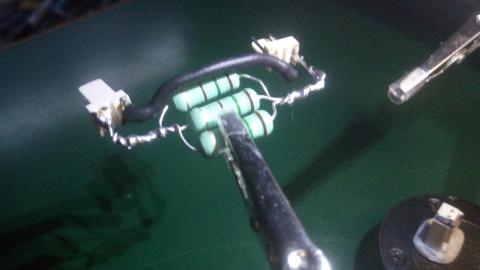
Join the resistor arrangement onto a pair of connector footings, taking care to observe the correct polarity for when these are connected onto the power supply and the LEDs. We achieve this by having one connector footing upside-down compared to the other, and with a negative wire joining the other two pins on the footings. The negative wire is left insulated, to help avoid short-circuits from occurring when the unit is potted and in-place.
Image 14
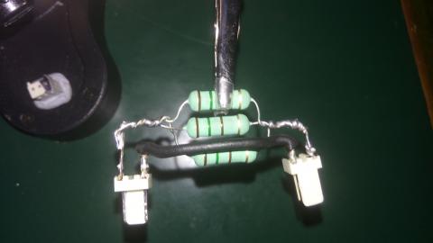
The same arrangement viewed from another angle. These connections are joined using solder to ensure a decent connection is made and to help reinforce the joins.
Image 15
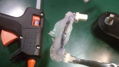
Then the whole assemblage is now potted using heat glue from a hot glue gun. Once it has cooled, it reinforces the whole structure holding it in shape and also helps to insulate the components from accidental short circuits from vibrations etc.
Image 16
Join the components together and check that it works. The positive wire from the LEDs is going into the switch and then exits into a connector linking into the resistor assemblage, and the negative wire from the LEDs goes directly to the connector. The other end of the resistor assemblage is connected to a 12-volt power lead with a connector on it, for testing the circuitry before closing everything up. The LEDs should light when the switch is activated. If they fail to light, check that you have wired each of the connector footings the correct way round (you don't want any reversed polarity) and likewise that the positive and negative wires from the LEDs are going into the switch and connector respectively, and also potentially that you have correctly observed the polarity of your power supply(!) - If those are all ok but still no LEDs light, then you probably have a bad connection somewhere - hopefully not in the glue-potted resistor assemblage, for that would now be difficult to correct at this stage, and it might actually be easier to simply make another resistor assemblage while taking better care to get that bit right, than trying to remove the cold glue with a scalpel for resoldering any of it. Or you might have a short-circuit somewhere (but this would usally blow a fuse and/or cause smoke and fire somewhere!). You should be able to tell which components are correct by checking each part for continuity using a multimeter.
Image 17
When it works OK, you can then put the parts into the enclosure and position the switch and set it all in place so that the switch can operate without disappearing into the enclosure when it is pressed (depending on the switch, some glue might be necessary here), and as long as you haven't used too much wire the components should all fit-in just about OK..!
Image 18 and image 19
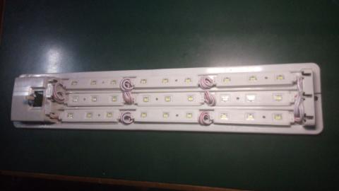
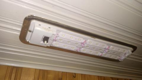
Now you can position the LED bars, three bars along each row and the rows running back and forth along the channels that the old strip light bulbs were in, taking care to coil up the surfeit of wire between each bar so that they all still fit along the channels. You can cut-off the tenth bar of LEDs and save it for using as a replacement should any of the others eventually fail. Don't join together the two ends of the last cut wire (i.e. they should NOT be joined together!) they should remain unconnected from each-other, and you could also use some heatshrink sleeving on the exposed ends of the last cut wires, as an added precaution against these accidentally short-circuiting to each-other. When all the LED bars are in-place you should still see it all still working correctly, as long as none of the wires joining the bars together have become broken/disconnected by the coiling-up that allows them to fit.
Image 20
You can now fix the light unit back in-place on the ceiling, reconnecting it to the 12v lighting power supply, and make one last check that all the LED bars are successfully stuck-down and not falling out of position.
Image 21
Then replace the lighting cover, and behold the magnificent awesomeness of your DIY light fixing and replacing powerfulness. You might well find that the LED configuration throws better light than the old strip lights used to, and the 50-ohm resistor ought to help these lights last longer than they would with no resistor, and certainly much longer than any strip light bulb ever does...


